OBSOLETE VERSION ... CLICK HERE for instructions for the newer hardware.
Only use these instructions if you have a PC board from the earlier version of the TactileAudio system.
Light Sensors
The TactileAudio system can use several different types of sensors, in addition to the touch sensors described in earlier chapters. In this chapter we'll show how to use a simple phototransistor and resistor to build a light-sensing input that triggers the audio files.
The short video below shows the basic features of light sensors for the TactileAudio project.
The Parts You'll Need
The AdaFruit TactileAudio Shopping List has the phototransistor and resistor you'll need.
The shopping list suggests a 1K-ohm resistor, which will work well for many indoor projects with normal lighting. However, if you expect to be in very bright light (such as outdoors) or very dim light (a dim room), you may need to change the value of the resistor.
Generally speaking, very bright light requires a lower resistance (e.g. 500 ohms or 220 ohms), and very dim light requires higher resistance (e.g. 2K, 5K, or even 10K ohms). You can easily find these on AdaFruit, and they are very inexpensive. If you think you may need to experiment, resistors are very cheap ($0.75 for a pack of 25), as are phototransistors ($0.95 each), so you can buy several phototransistors and various resistor values, and experiment to find the best value.
Solder the Phototransistor, Resistor, and Wires
To generate the signal needed by the Teensy, we need to solder a phototransistor and resistor in series, with the sensor (yellow) wire at the junction. The photos below illustrate how to do this.
Be sure you use the correct leads of the phototransistor; one is longer than the other.
Note that there are two configurations; select the one that fits your project.
- Light-on: Light starts the audio track and/or vibration, dark stops it.
- Light-off: Dark starts the audio track and/or vibration, light stops it.
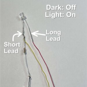
Figure 1: Dark-Off / Light-On
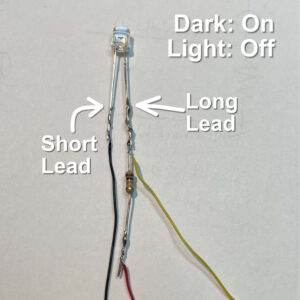
Figure 2: Dark-On / Light-Off
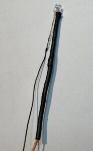
Figure 3: Heat-Shrink over resistor
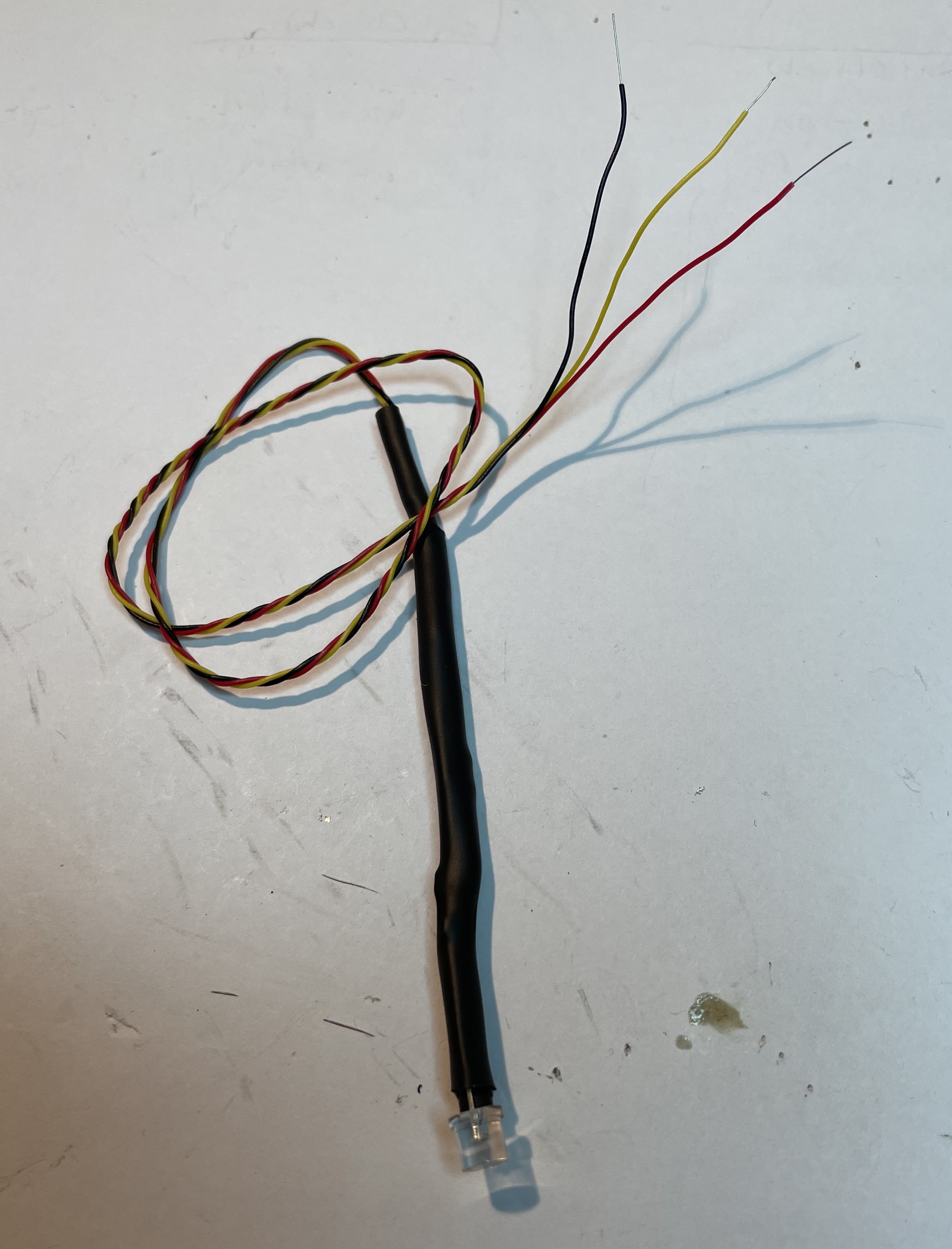
Figure 2: Finished Sensor
Steps:
- Cut three wires (yellow, red, and black) to the length you'll need. Do not twist them together yet!
- Strip the insulation back about 3/4 inch (2cm) on each wire.
- Hold the resistor and the stripped end of the yellow wire together, and wrap them around lead of the phototransistor (short or long lead, depending on your configuration; see Figures 1 and 2 above). Solder the resistor and yellow wire to the phototransistor.
- Solder the red and black wires to the other lead of the phototransistor and the resistor (consult Figure 1 or 2 to see where the red and black wires go)
- See Figure 3: Slip a piece of small-diameter heat-shrink tubing over the two wires that go to the resistor, and use heat (a match or lighter) to shrink it tight.
- See Figure 4: Slip a shorter piece of the next-larger-diameter heat-shrink tubing over all three wires, and slide it up against the phototransistor, and shrink it with a heat source.
- For neatness, you can now twist the three wires together.
Connect Phototransistor Sensors to Teensy:
You connect the phototransistor sensor to the Teensy exactly like connecting a Gemma-M0. See this video for details.